
301 Moved Permanently
The solar industry is booming, and the increase in PV installations has challenged system designers, manufacturers and standards organizations. Indeed, the requirements of large-scale PV applications are unique, especially in terms of current, voltage and ambient operating temperature.
Studies of all parameters are recommended to identify the appropriate overcurrent protective devices. A focused and systematic approach to power system analysis helps enhance performance and design, validate equipment selection, and simulate response to out-of-the-ordinary conditions. At the onset of a solar project, typical analysis includes (but is not limited to) short-circuit, arc flash and load flow studies:
- Short-circuit analysis determines the necessary characteristics, ratings and settings for electrical protective devices;
- Arc flash studies calculate arc flash hazards associated with energized components at locations throughout the power system in accordance with the latest National Fire Protection Association and National Electrical Code (NEC) requirements; and
- Load flow analysis assesses the system’s capacity to supply electrical energy from renewable energy sources to the utility or end user.
Basics
The goal of overcurrent protection devices (OCPDs) aligns with typical project goals - optimizing renewable generating capacity while enhancing safety. OCPDs protect solar balance-of-system equipment, support reliability and protect wiring devices connected from the module to the combiner or inverter. There are many fuse and circuit breaker solutions available. The challenge is not in the availability of a solution, but in picking the appropriate technology that balances performance and reliability.
Unlike typical grid-connected AC systems, the available short-circuit current within PV systems is lower, and OCPDs need to operate effectively on low fault current levels. U.S. and international standards organizations understand that PV systems have different requirements from traditional electrical systems. The specific characteristics OCPDs need to meet in order to protect PV systems are defined by Underwriters Laboratories (UL) 2579 for fuses and 489B for circuit breakers, as well as International Electrotechnical Commission (IEC) 60269-6 (gPV). OCPDs for string and array protection should also be designed to meet these standards.
Fuses in PV systems should be fully tested to the requirements of IEC 60269-6 and meet UL 2579 requirements, which are similar to the IEC standards. PV fuse current ratings are defined by the performance requirements of IEC and UL standards in order to protect PV modules during overcurrent events. These ratings do not reflect a continuous service rating and should be reduced at increased ambient operating temperatures. Fuses should not be subject to a continuous current of more than 80% of the rated UL or IEC ampere rating.

Molded case circuit breakers and molded case switches adhere to different standards. These devices should be fully tested to meet and exceed the requirements of UL 489B. The performance requirements set by this UL standard establish the current ratings assigned to PV circuit breakers to protect PV modules during overcurrent events. For applications where ambient operating temperatures exceed 50°C, the service rating should be reduced. Circuit breakers for PV applications are rated at either 80% or 100%, depending on their performance characteristics.
Beyond these basic requirements, there are a host of other national and local code requirements for PV systems. Initially, the industry used UL 67 and 891 standard switchboards and panelboards for 600 VDC installations. As installations have increased in size, standards have evolved. The UL 1741 standard established the requirements for inverters, converters, controllers and interconnection system equipment. The application of this standard has been somewhat confusing, as local inspectors believed that all DC-rated solar PV products should meet this requirement.
Evaluating system requirements
Depending on the PV system configuration and capacity, several PV output circuits may be connected in parallel. The OCPD on each output circuit will help protect conductors from fault currents and enhance safety. It will also isolate the faulted PV output circuits so the rest of the system will remain energized.
String protection
PV systems that have fewer than three strings will not generate sufficient fault current to damage the modules in the event of a short circuit. As a result, they do not present a safety hazard when the conductor is sized correctly for local code and installation requirements.
Systems with three or more strings connected in parallel need to incorporate protection for each string. A fuse in each string will protect the conductors and modules from fault currents and help enhance safety. These devices should meet IEC 60269-6 requirements. Devices that also meet the UL 2579 standard can be used to protect PV modules in reverse current situations. Fuses can also isolate the faulted string so the rest of the PV system can continue to generate electricity. Ambient operating temperatures need to be considered when selecting fuses. PV module current output varies with temperature and sun exposure.
A DC molded case switch and disconnect switch provide different means of disconnect. The molded case switch can provide the dual function of a disconnect means with remote OFF operation. This functionality helps meet NEC 2014 690.12 rapid shutdown requirements designed to help first responders disconnect a PV system from a building’s electrical system in the event of an emergency situation or fire.

Array/inverter protection
The maximum power point of modules can vary substantially, and manufacturer-specified short-circuit current and reverse current characteristics should be used to select PV fuses. Additionally, ambient temperature needs to be considered, as it impacts the module’s current and voltage output.
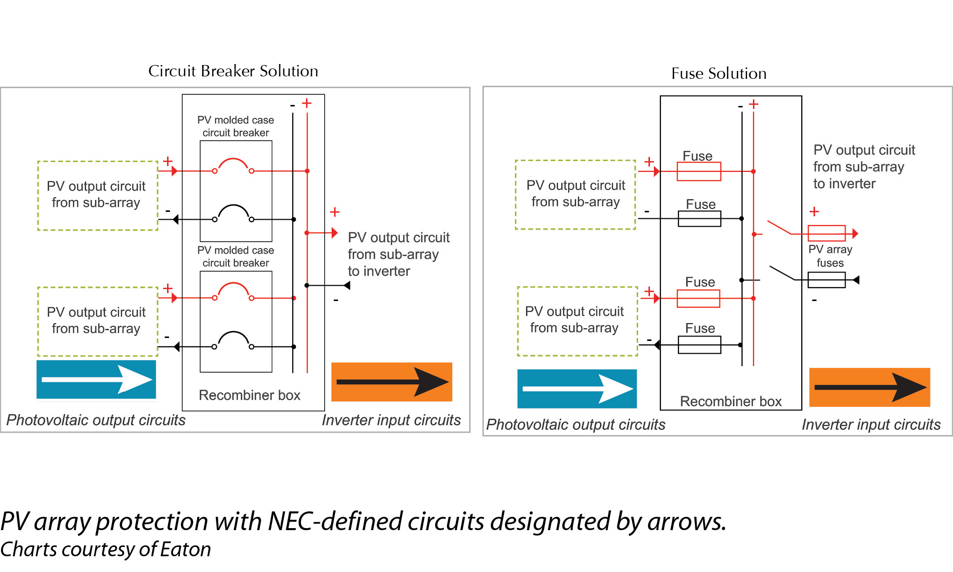
An OCPD positioned in the conductor that carries the combined power output from a number of PV circuits should be protected by a PV output OCPD. If the number of PV output circuits are combined prior to the inverter, then another OCPD should be incorporated. This is called the inverter input circuit.
Both fuses and circuit breakers can be used for output circuit protection. Key considerations for these OCPDs include the voltage rating per NEC table 690.7 and ampere rating, as additional de-rating may be required for high-ambient-temperature installations. Additionally, calculations should verify system voltage, ampere rating and conductor size.
PV circuit breakers are available in 600, 1,000 and 1,500 VDC models with either 80% or 100% ratings. The benefit of the full, 100% rating is that the maximum amount of electric current a conductor can carry can be applied; there is no de-rating needed, and the breaker and conductor size can be reduced. Circuit breakers with an 80% rating should be de-rated by a factor of 1.25.
If a number of PV circuits are combined prior to the inverter, then another OCPD should be incorporated. These OCPDs can be mounted either inside the inverter or in an external recombiner panel. Recombiners are typically designed for systems in excess of 1 MW. This equipment incorporates circuit breakers to protect the incoming cables and solar inverter components. Recombiners should be tested and certified by UL to the 1741 marking to reduce downtime and meet performance requirements in harsh applications. These assembled products should be secured from manufacturers with proven knowledge of group-mounted products, taking into account installer/end user concerns, including cable bending space, ease of installation, component consolidation and enclosure durability.
Fuses designed for solar inverter protection are available in a number of physical sizes, with ratings up to 1,500 VDC and 630 amps.
Closing thoughts
Over the last 50 years, PV power generating systems have evolved into a mature, sustainable and adaptive technology. The unique nature and size of these systems necessitate the need for new and effective electrical protection products, and the available solutions will continue to evolve and new standards will be introduced. By taking into account the considerations to properly protect your PV electrical systems, you can optimize your renewable energy power generation capacity, ensuring your equipment is safe, efficient and reliable.
System Protection
Selecting Overcurrent Protection For Utility-Scale Solar Projects
By Mitchell Barrineau
Understanding applicable codes, standards and available solutions will enhance safety, reliability and power generation.
si body si body i si body bi si body b
si depbio
- si bullets
si sh
si subhead
pullquote
si first graph
si sh no rule
si last graph