In many applications, engineers and designers face a decision to specify one large-capacity unit, or multiple smaller units. It is the same with solar inverters.
In a solar field application, the inverter is the most critical balance-of-system component. The inverter is the only component with active electronics containing protection circuitry that will trip or fault to protect itself, giving it the highest likelihood of failure. The solar panels and the transformer make up the other significant components in the field. As passive pieces of equipment, they are less likely to cause any drastic performance issues based on usage, weather or reliability.
One central unit can be specified and sized to harvest the peak amount of energy available from an array. That unit will often be very lightly loaded, with subsequent inefficient operation. If that unit does fail, the entire array is offline, and no revenue is generated. Many times, reliability and availability dictate the use of multiple smaller devices. There are several benefits from this approach, including the following:
- Under light or intermittent loading, a minimum amount of capacity is brought online. This reduces energy consumption and often can improve regulation and efficiency.
- Reliability is enhanced because units are allowed to rest when not needed. There is less wear and tear on all the units when they are rotated.
- The failure of an individual unit will not bring the entire process to a standstill.
{OPENADS=zone=72&float=right&margintop=10px&marginleft=10px}
In a solar application, it is not uncommon to use multiple inverters; for example, a 2 MW array may have four 500 kW inverters, with 25% of the array dedicated to each inverter. This provides some buffer against failure, because a single inverter fault will affect 25% of the array, and not the entire field. However, each inverter must always be on, so that each inverter will still spend a high percentage of the time lightly loaded and inefficient.
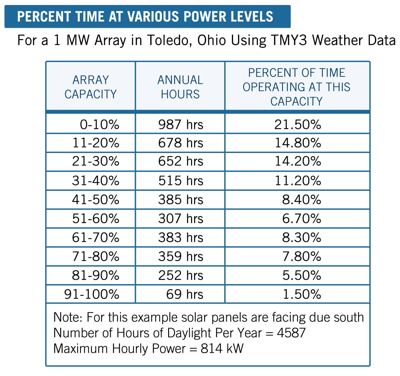
In a conventional array with either one larger inverter, or three or four central inverters, the conditions that inhibit maximum output are inefficient operations during low-light levels, high impact of downtime and increased downtime during service. In the midsection of the U.S., 35% of the time, the array is generating less than 20% of its rated capacity. That is a considerable amount of time to have all the inverters operating in an inefficient state. Refer to the chart for the associated percentage of time the capacity of an array is used throughout the year.
The chart below shows typical conditions in the most populous areas of the U.S. This data reveals that the majority of the time is spent at low energy output levels.
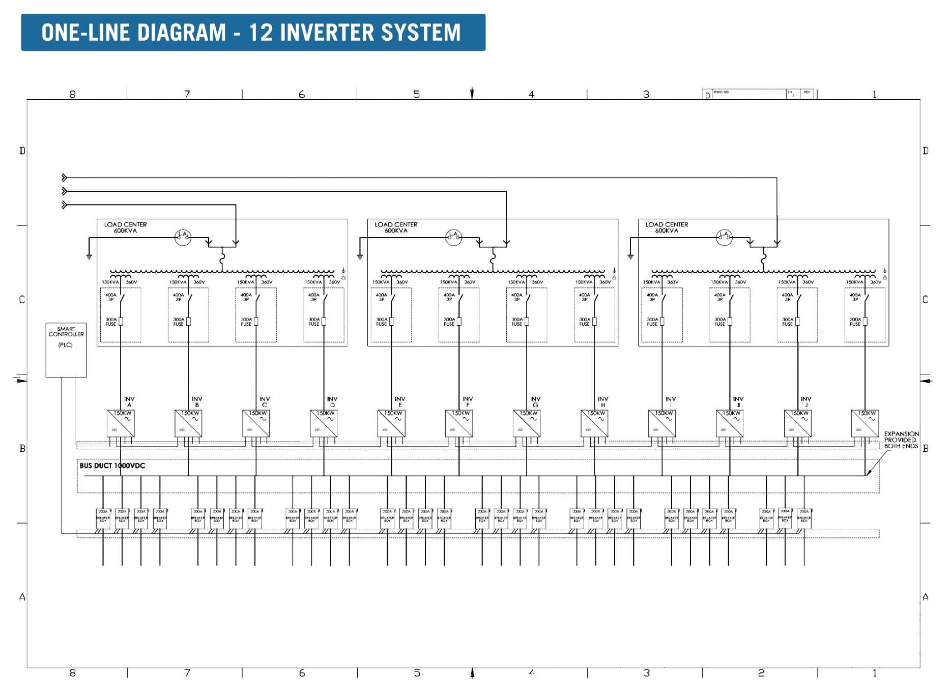
Under a distributed architecture, multiple inverters are dedicated to an array such that the entire array – up to 2 MW – is available to feed every inverter via a DC bus. In this configuration, all the available energy is available to feed as few inverters as needed at any moment.
In the diagram below, a multiplicity of modest-size (165 kW) inverters are connected to the DC bus, and each inverter, in turn, feeds a dedicated input on a load center transformer. In the example, three load center transformers each have four inverter inputs. Field mounted combiner boxes each feed one of the breaker boxes, where the current is monitored, and these breaker boxes are physically and electrically connected to the DC bus. A smart controller takes care of the operation and monitoring.
At the end of each day, the smart controller reads the operating hours of each inverter and establishes a sequence for the next day's operation. Each inverter has three modes: standby, master or slave. The unit with the fewest operating hours begins the day as master, and subsequent slave units are brought on as needed in the order of their operating hours. The next day, the sequence is rotated, ensuring equal run times for all units.
It takes as little as 650 W of solar power to start exporting energy to the grid. So, every morning, every evening, and during overcast conditions, the system expands the operating window by funneling all the available energy to only one inverter, which starts exporting energy at 650 W.
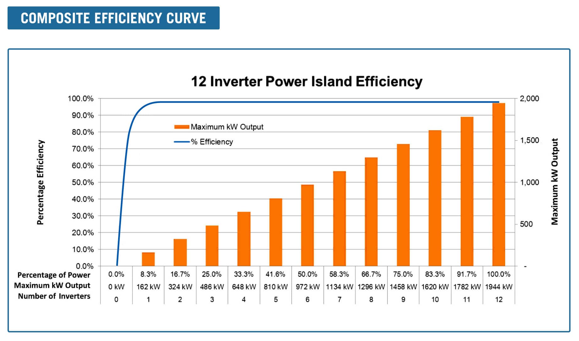
With a 2 MW, 12-inverter system, the composite efficiency curve is shown in the chart below. Note that the inverter system is operating at peak efficiency at less than 2% of the system output.
The master inverter is responsible for the maximum power point tracking (MPPT) function for that day. Using a ‘perturb and observe’ routine, the master inverter sets the operating current for the entire array, communicating those instructions to every inverter. However, only the inverters that are on are acting on that signal. When the first inverter reaches 85% of its capacity, the next one is brought on, in slave mode. This is repeated until solar noon, when all inverters are on.
As the day wanes, inverters are pulled off, until at the end of the day, the only one left running is the one that started the day. This describes a fully sunny day; it gets more interesting on a partly cloudy day. The inverter system must not only follow the changing sunlight level via the MPPT function, but it must add and shed inverters in response to the available energy. In order to minimize switching transients, the current is ramped to zero prior to switching inverters, and hysteresis is used such that power and time thresholds are used to determine the switching behavior.
All of this results in excellent MPPT tracking, and an operating sequence that results in each inverter spending approximately 40% of the available daylight operating, and 60% of the time resting.
Distributed architecture results in improved reliability, uptime and availability. If an inverter faults, it is bypassed, such that there is no impact on energy production except for a small amount of clipping near solar noon on a sunny day. With one unit faulted in a 12-inverter system, energy loss ranges from zero on an overcast day to less than 3% of nominal production on a sunny day.
Each inverter has both DC and AC disconnects to allow it to be completely isolated for service. A blown fuse or loose termination can be fixed quickly with no interruption of array output from the other inverters. A problem in the ‘core’ inverter would result in that unit being replaced with a spare unit.
Using a distributed inverter architecture design maximizes the field performance and return on investment of any given solar field between 500 kW and 10 MW. The built-in reliability of multiple inverters, the lower power threshold needed to start the energy production process and the lower per unit use of each inverter present the distributed architecture design as a superior solution for solar installations.
Peter Gerhardinger is vice president of technical sales at Nextronex Energy Systems LLC in Toledo, Ohio. Reach him by email at peterg@nextronex.com.
